what is the issue with UML?
- closely connected with OOP
- propagates object-oriented modelling
- however the design should not consider the implementation
C4 model
- hierarchical set of software architecture diagrams
- different levels of abstraction for different audience
- has four levels:
- context, containers, components and code
- popularized by Simon Brown
this chapter is based on c4model.com
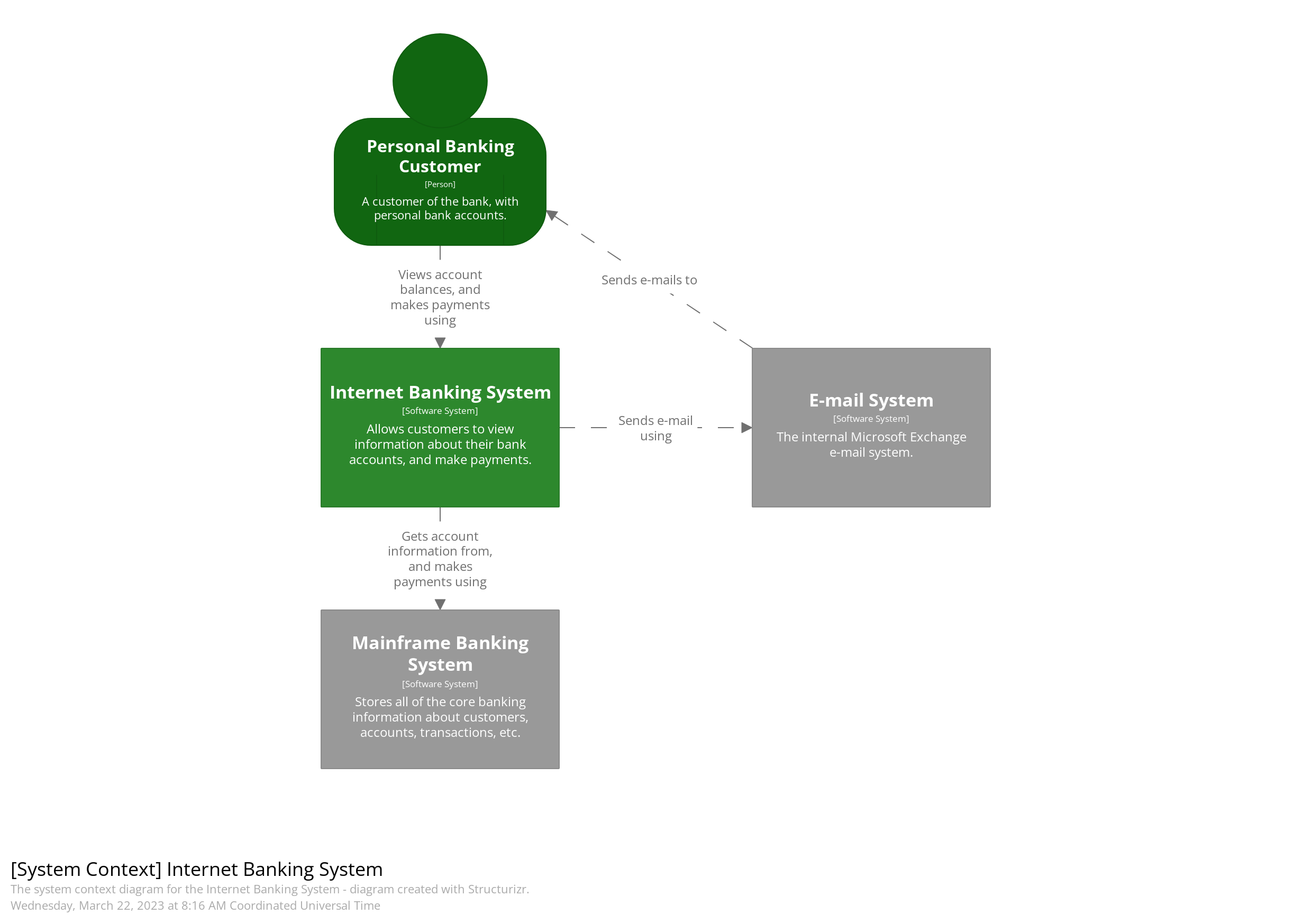
Level 1: System Context diagram
- high level relation with other systems or users
- similar to use case diagram
- technologies, protocols and other low-level details are not important
- understandable for non-technical people
Shows the software system you are building and how it fits into the world in terms of the people who use it and the other software systems it interacts with.
Simon Brown - The C4 Model for Software Architecture
system context example
notation

Level 2: Container diagram
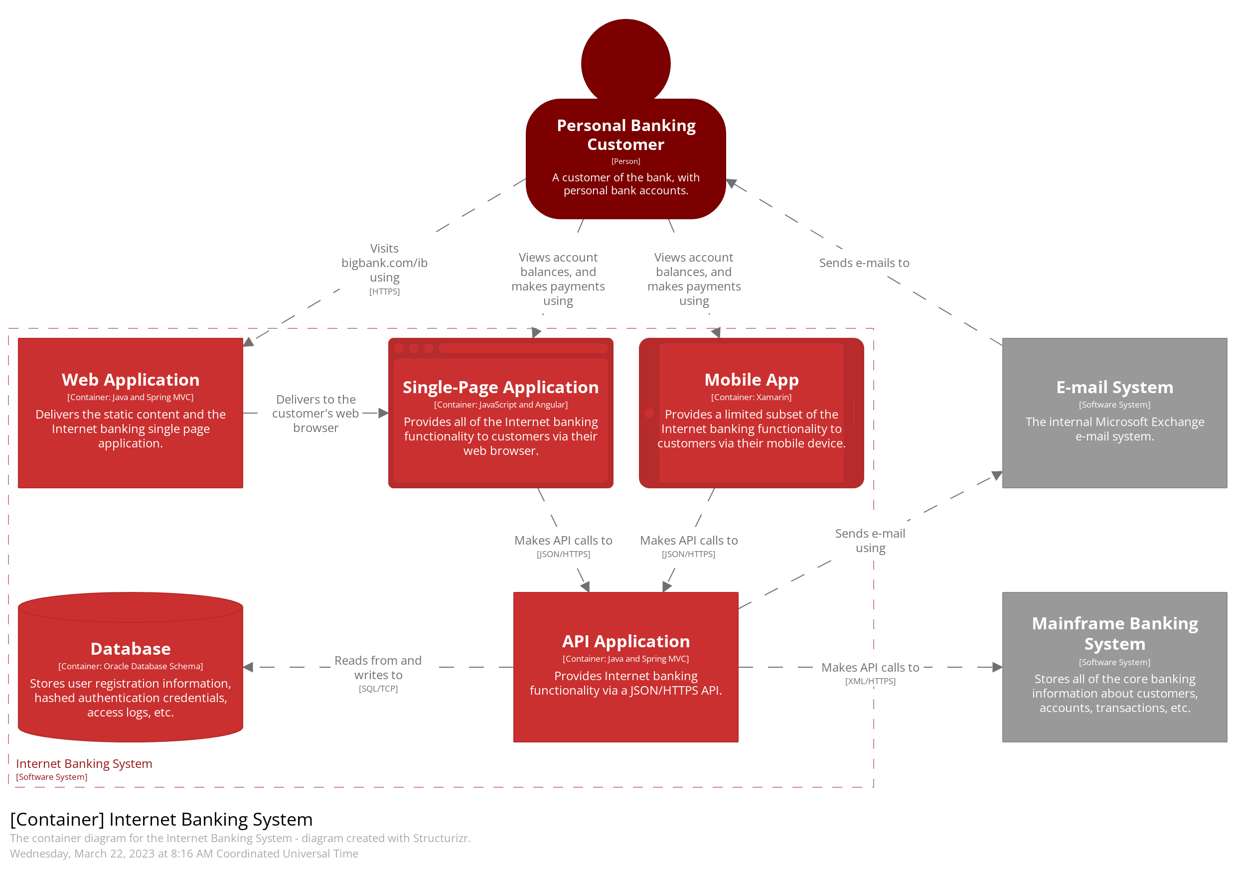
Zooms into the software system, and shows the containers (applications, data stores, microservices, etc.) that make up that software system. Technology decisions are also a key part of this diagram.
Simon Brown - The C4 Model for Software Architecture
container example
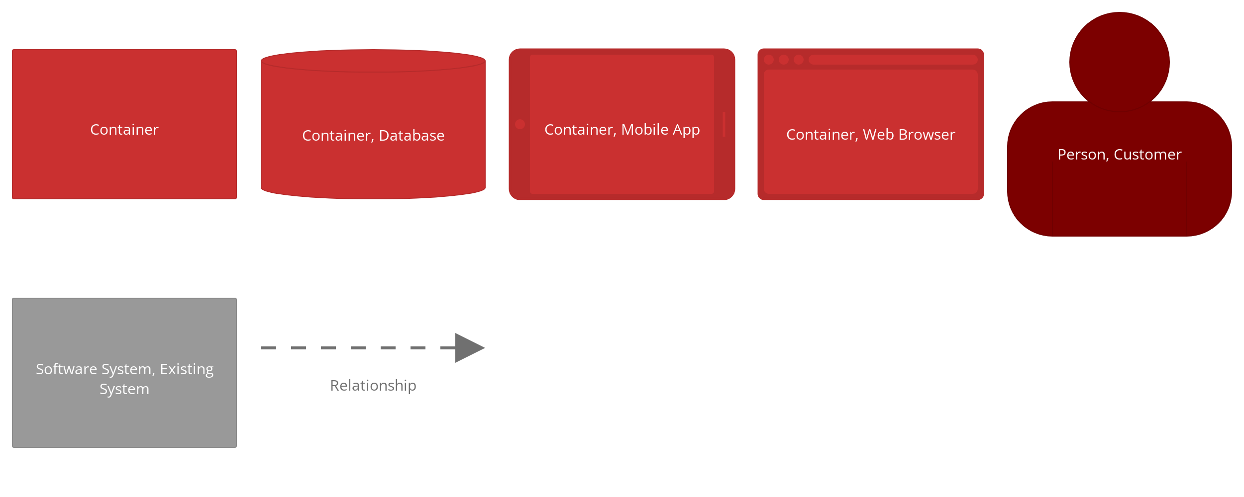
notation
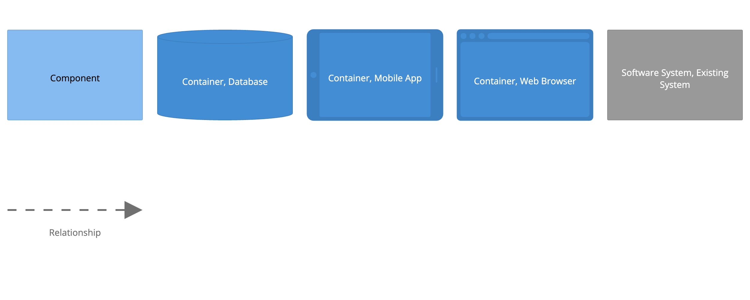
Level 3: Component diagram
Zooms into an individual container to show the components inside it. These components should map to real abstractions (e.g., a grouping of code) in your codebase.
Simon Brown - The C4 Model for Software Architecture
component example
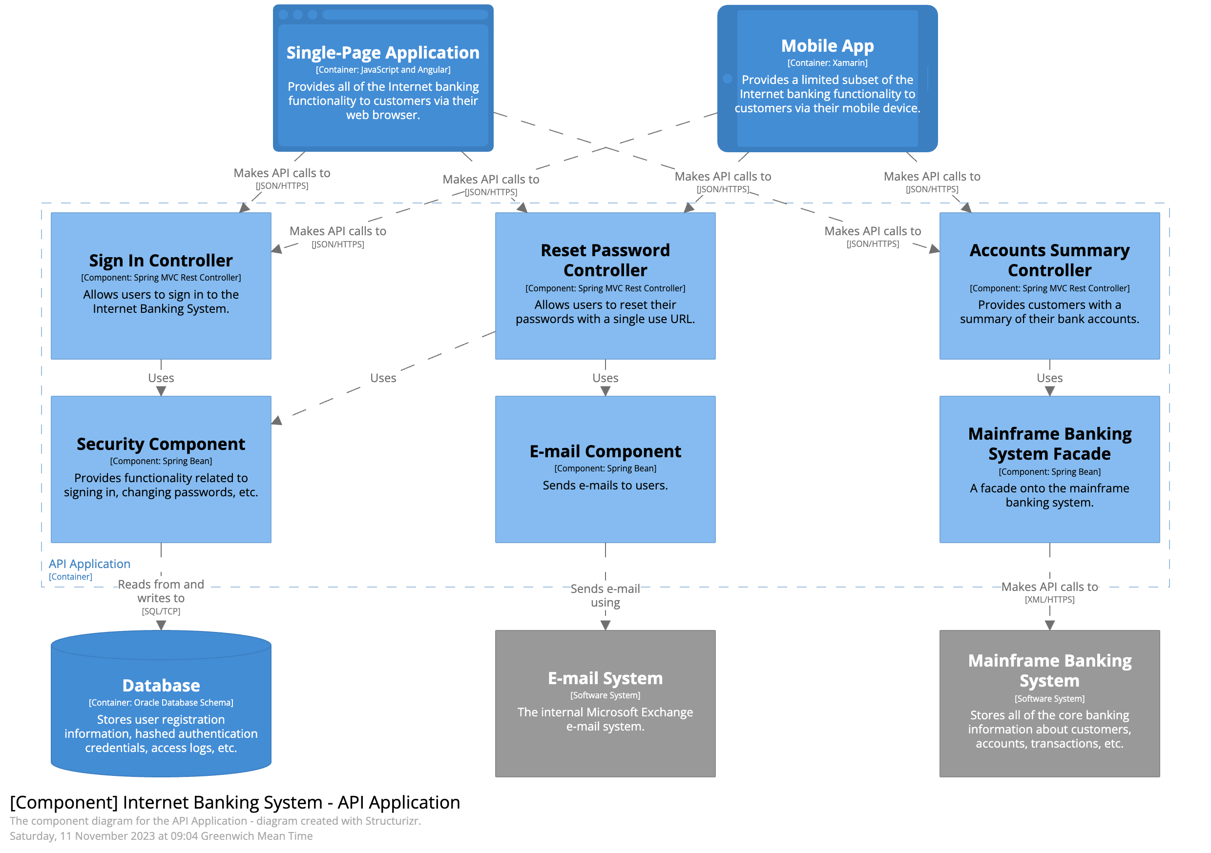
notation
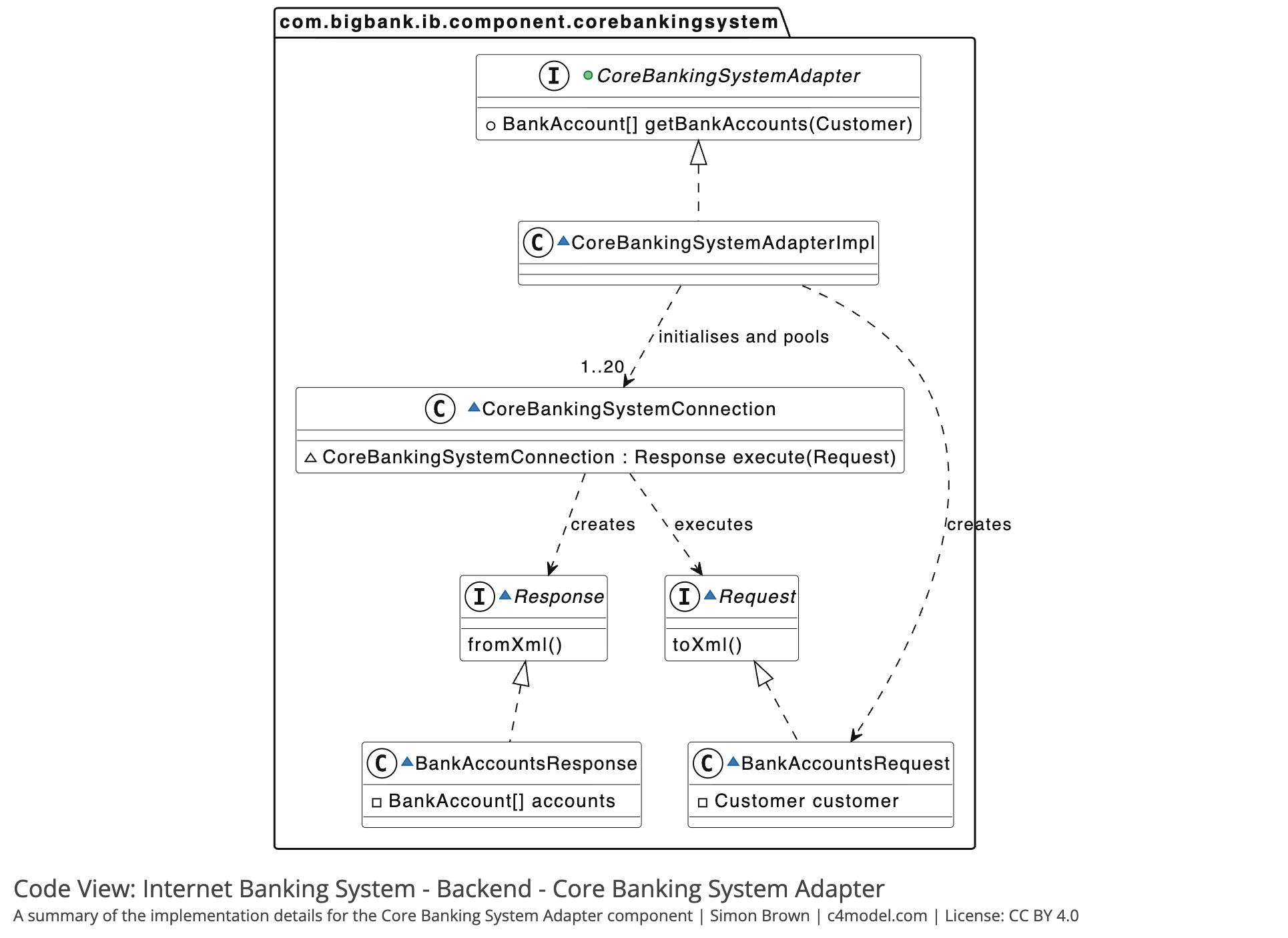
Level 4: Code
Finally, if you really want or need to, you can zoom into an individual component to show how that component is implemented.
Simon Brown - The C4 Model for Software Architecture
code example
additional diagrams in C4 model
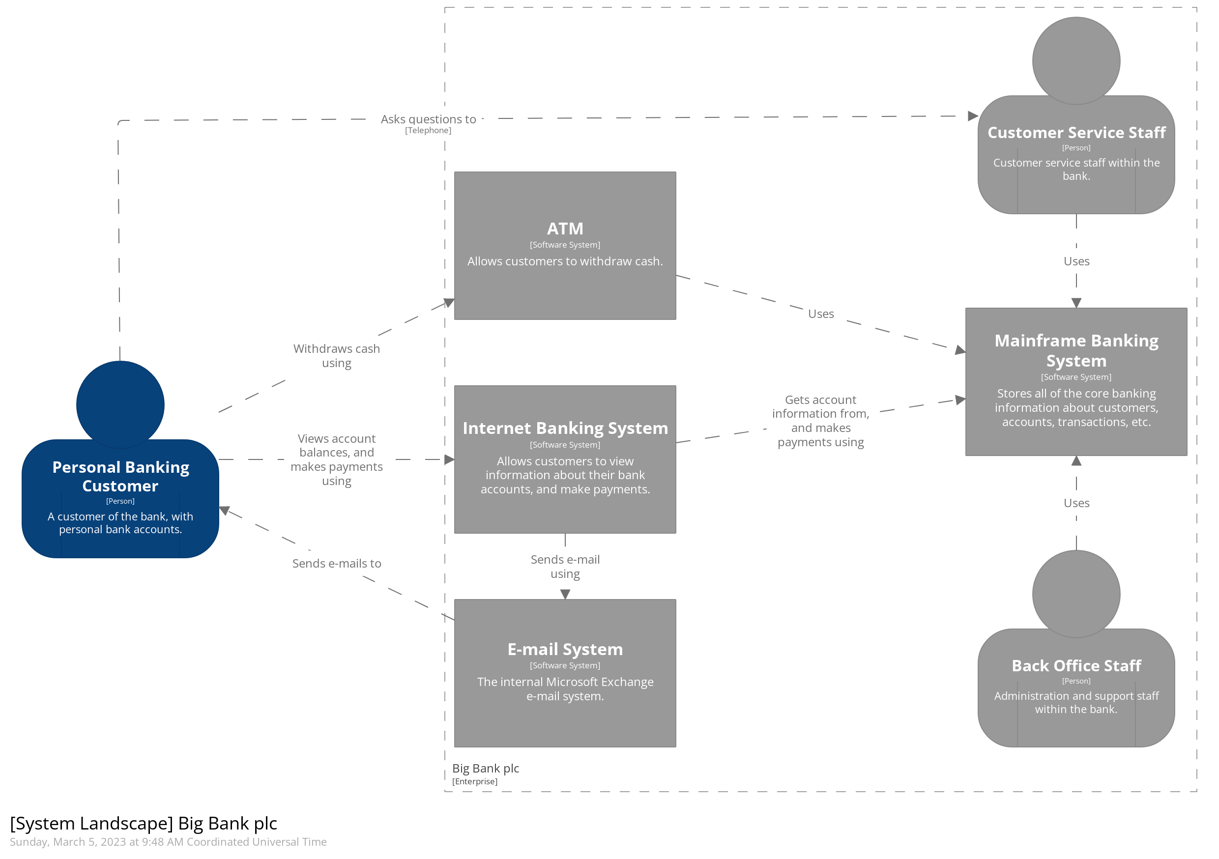
- system landscape diagram
- even broader environment than the system context diagram
- dynamic diagram
- based on the UML communication and sequence diagrams
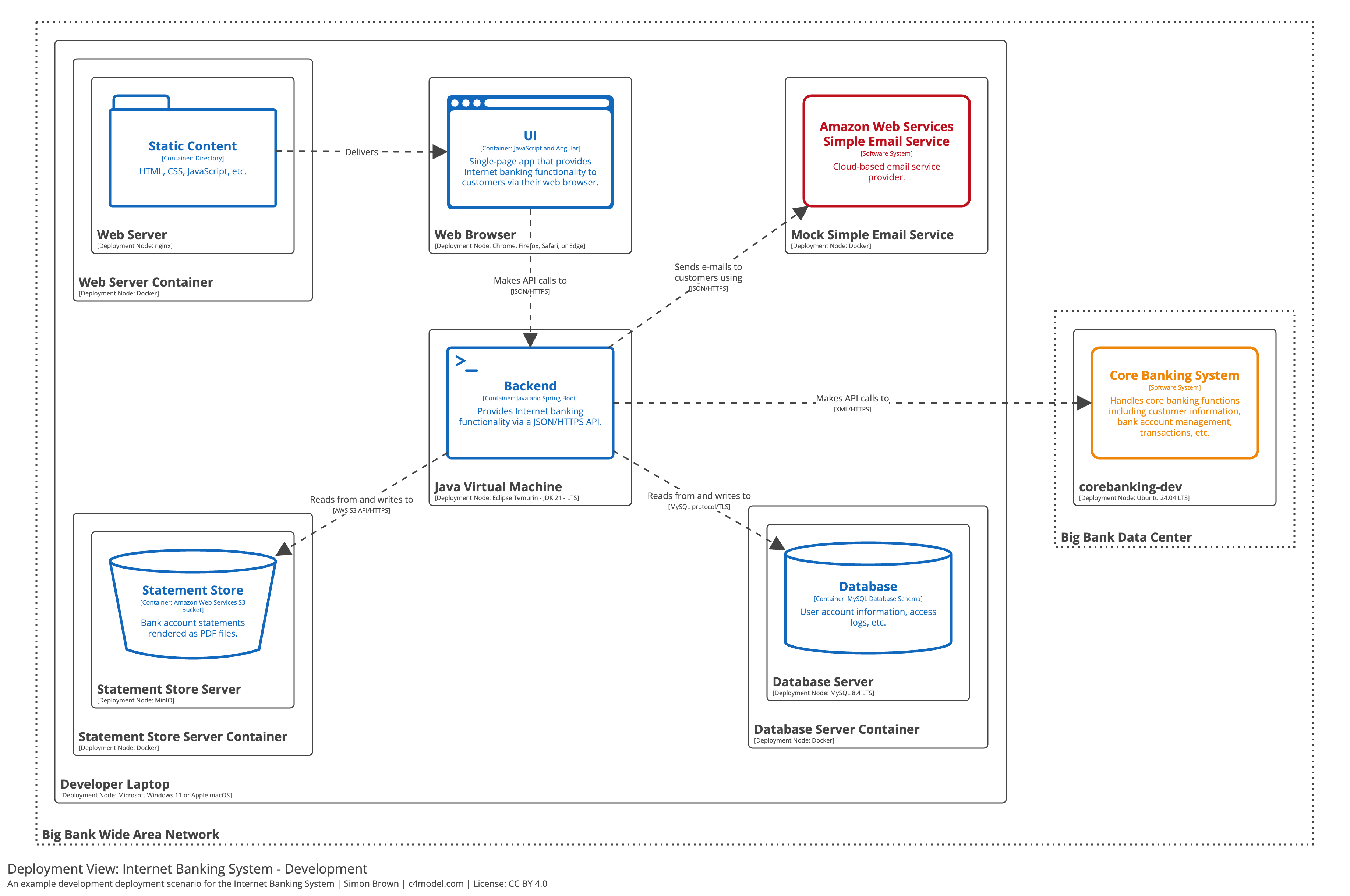
- deployment diagram
- based on the UML deployment diagram
system landscape diagram
dynamic diagram (collaboration style)
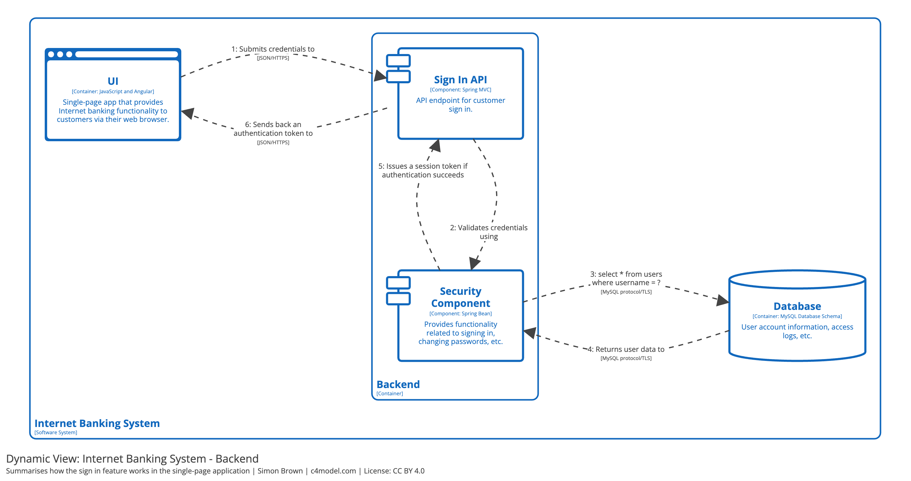
dynamic diagram (sequence)

deployment diagram
- shows where an instance of a software system is running e.g.,
- physical infrastructure (e.g. a physical server or device)
- virtualised infrastructure,
- containerised infrastructure (e.g. a Docker container),
- an execution environment (e.g. a database server, Java EE web/application server, Microsoft IIS), etc.
- deployment nodes can be nested
summary
overview first, zoom and filter, then details on demand
– Ben Shneiderman
suggested software
- Google Drawings
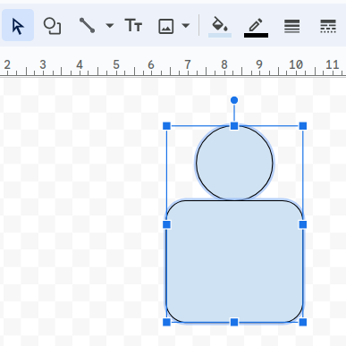
- it does not have a person shape though, but can be constucted from a circle and a rectange
- Excalidraw
- has a plugin for drawing C4
- Visio
